Friday, December 5, 2014

VISUAL REVOLUTION OF THE VANISHING OF ETHAN CARTER

VISUAL REVOLUTION OF THE VANISHING OF ETHAN CARTER

  • 25 MARCH 2014 | AUTHOR:  | CATEGORY: ETHAN CARTERGAME DESIGN


    This…
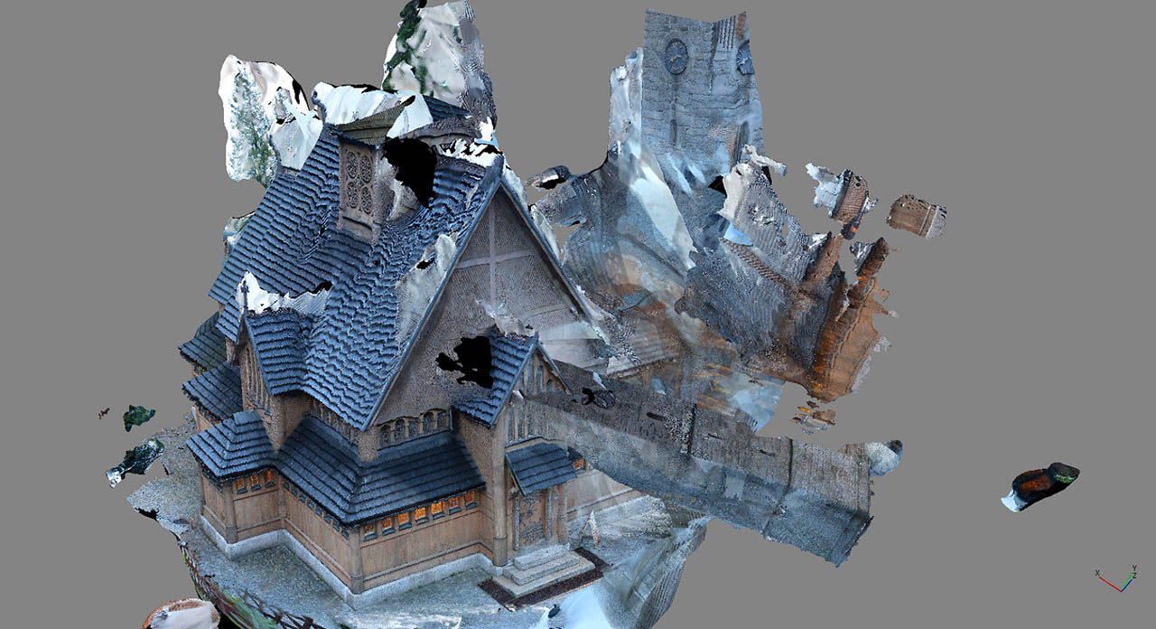
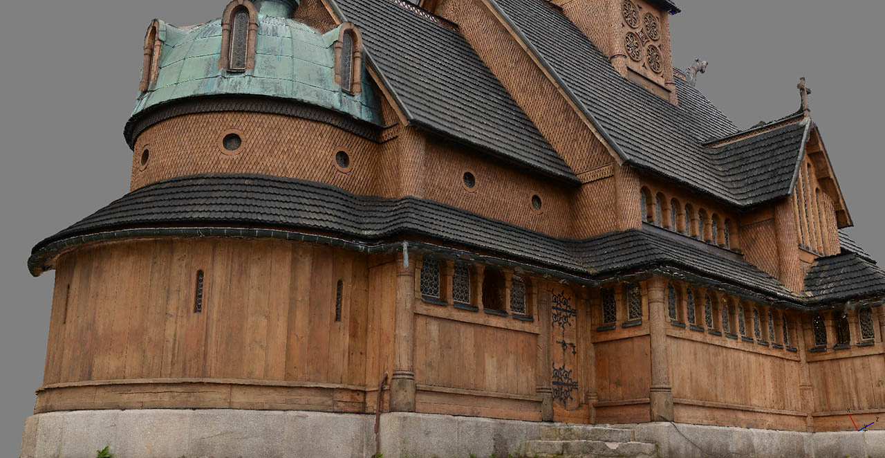
    Photogrammetry - Church
    …is not a photograph. It is actual 3D model of a church from our game. Before I tell you all about how we created such photorealistic assets (and, maybe surprisingly, why we are not using them in fully photorealistic way in our game), let us think about what makes it look real.
    Look around you – do you see any tiling textures?
    You shouldn’t, but if you do – look closer. That brick wall or those floor tiles are not, contrary to popular belief, a textbook definition of tiling. Look how some edges are more worn out than others, how some parts seem smoother than others, how dirt and dust settled in certain areas. Some parts may be chipped off, some areas stained, on some parts mold or rust started to settle… Ok, maybe those last ones are not in your fancy neighborhood, but you get the point.
    And it’s all not random either. If you really wanted it, you could probably make sense of it all. The floor might be more worn out around the front door, or where your chair wheels constantly scrub a patch of the floor, and the outer wall might be darker from the side that gets hit by the rain more often, etc.
    You could make sense of it all, but who cares? Your brain usually doesn’t – it’s real, it’s normal, nothing to get excited about. However, your brain does take notice when things are not normal. Like in video games. Even if on the unconscious level, your brain points out to you all those perfectly tiling textures, all those evenly worn-out surfaces, those stains placed in all the wrong places – and whispers in your ear: LOL!
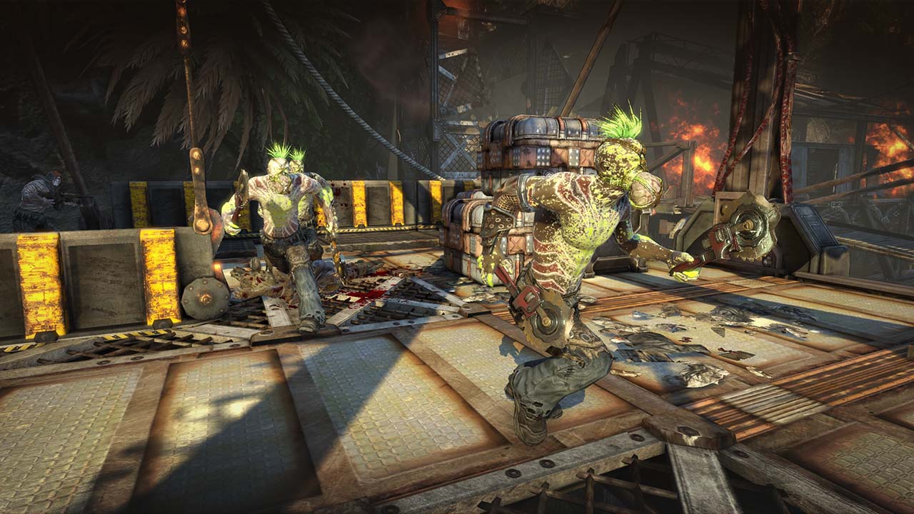
    I’m really proud of Bulletstorm — I directed all of environment artist’s efforts — but well, sometimes art was just as crazy as the game itself. Take a look at this floor surface, does it seem right to you?
    Photogrammetry - Bulletstorm
    It’s not that technical limitations prohibit developers from creating things that feel right, not on modern PCs and consoles anyway. The problem – if we put time and money constraints aside – is that more often than not the graphics artists’ brains don’t care about the conscious analysis of reality either. We can be as quick as you to point out unrealistic looking asset in other games, but we rarely stop to think about our own work. Need to make a brick wall texture? Basically a bunch of bricks stuck together? Old-looking? Sure thing boss! If we’re diligent, we may even glance at a photo or two before we get cracking. But even then, quite often we look but do not see.
    In The Vanishing of Ethan Carter, you’ll see some of the most realistic environment pieces ever created for a video game. Assets are no longer simplistic approximations of reality – they are reality. But it’s not that somehow we have magically rewired our brains to be the ideal reality replicators…
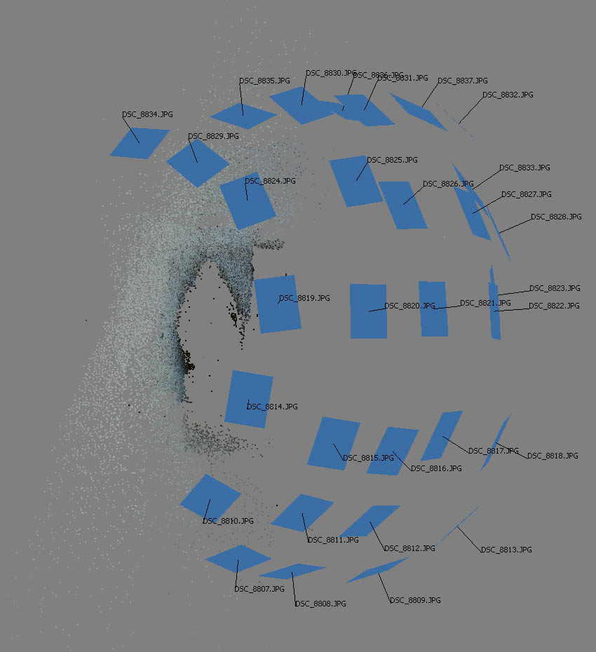
    With photogrammetry, we no longer create worlds while isolated from the world, surrounded by walls and screens. We get up, go out there and shot photos, lots of photos. And then some. Afterwards, a specialized software — we are usingPhotoscan from Agisoft — looks at these photos, and stares at them until it can finally match every discernible detail from one photo to same exact feature in other photos taken from different angles. This results in a cloud of points in 3d space, representing real world object. From there, the software connects the dots to create a 3d model, and projects pixels from photographs to create a texture.
    I’ll spare you the details about Lowe’s Scale Invariant Feature Transform (SIFT) algorithm, solving for camera intrinsic and extrinsic orientation parameters and other details of what that software does – all that matters is that you feed it withgood photos taken around some object and you get the exact replica of that object, in 3D, in full color, with more detail than you could ever wish for.
    Take a look at this slideshow to better understand the process of turning a bunch of photos into an amazing game asset:
    You can find extra video in today’s post on our Tumblr.
    Photogrammetry is incredible. I have been making games for 20 years, I have worked with amazing talented artists on huge AAA blockbusters like Bulletstorm or Gears of War, and you could say I am not easily impressed in the art department. But each new photoscan gets me. So much detail, so many intricacies, but most importantly, all of them just make deep sense. Cracks, stains, erosion – Mother Nature has worked a billion years on some of these assets, it’s almost unfair to expect comparable quality from artists who spend no more than few days on similar assets.
    Enough convincing, see it for yourself. We have found a pretty new and unique way to let you experience photogrammetry of The Vanishing of Ethan Carter. What follows below is not just static screenshots of our game assets. After you click on the image, a 3D object is loaded, then the texture downloads and voila, you get to experience early glimpse into our game world.
    You can orbit, pan and zoom camera around these objects, or just sit back and let the automatic rotation showcase them. I highly recommend to take charge of camera (hold down LMB, rotation direction depends on the position of the mouse pointer in the image), especially after going full screen, to fully experience the detail and quality of these assets.
    Speaking of quality – these are raw unprocessed scans, and some of them are actually lower res than what we have in the game.
    Twenty six photos covering same boulder from every possible angle, and you get this:
    39 photos taken around a cemetery statue, and you get this:
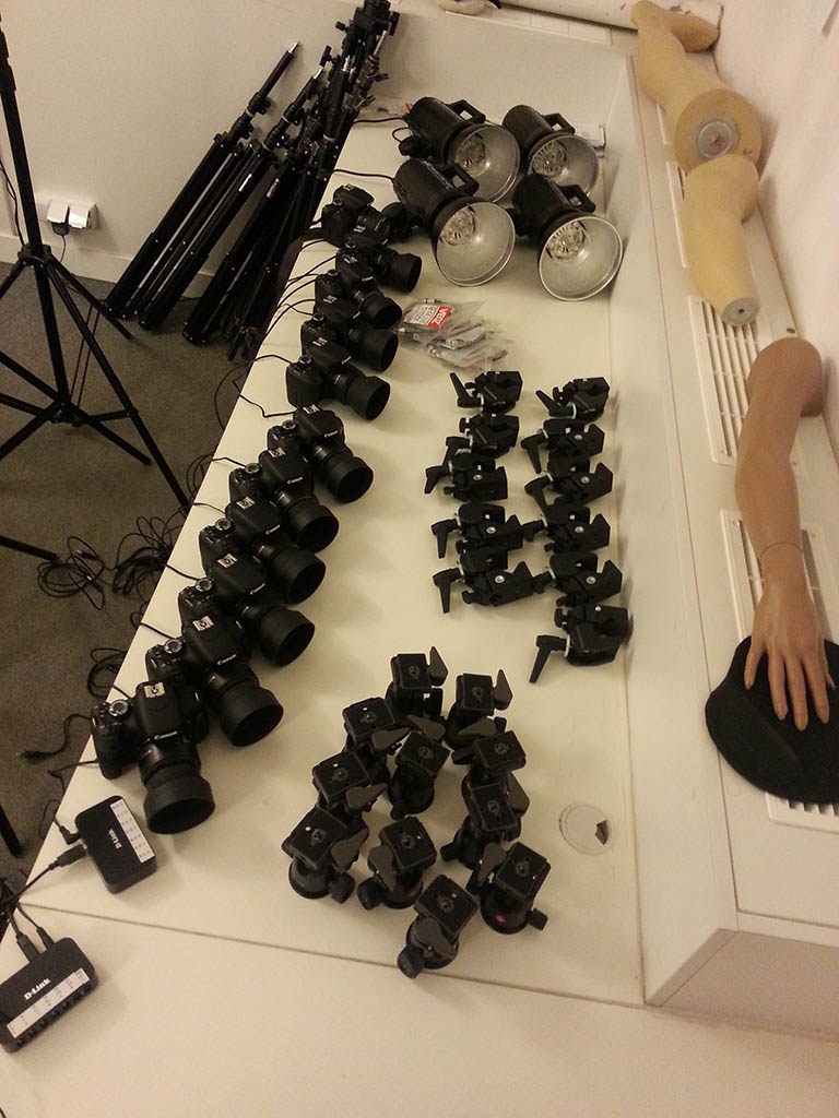
    Photogrammetry gets confused by moving subjects. If you want to scan human face, even tiny head/facial muscles movement between photos means errors in scan and lots of manual cleanup and resculpting. But you can get around that issue, with this:
    Photogrammetry - Gear
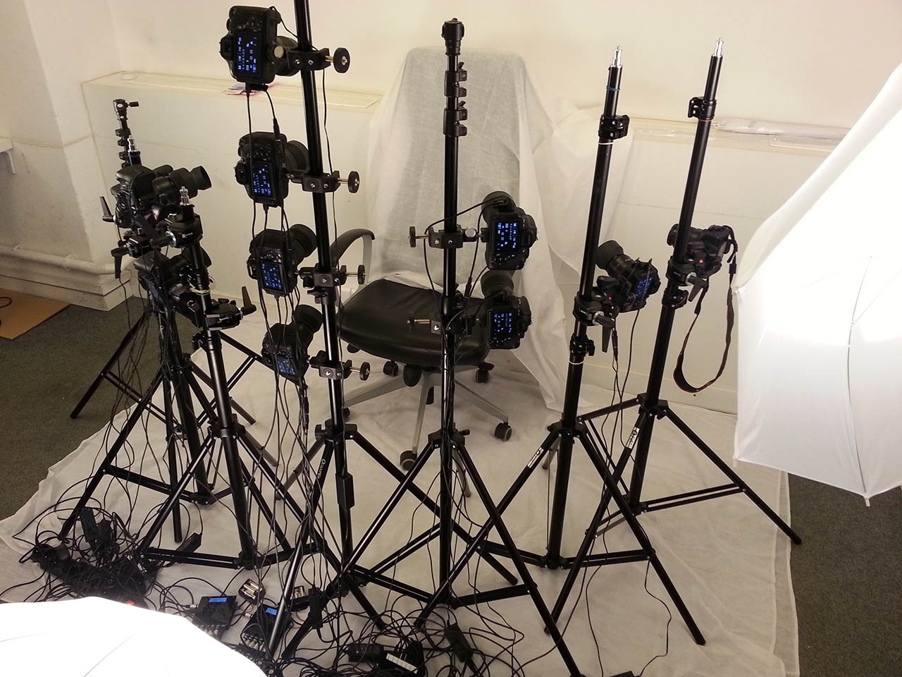
    Fake plastic hand is optional. You set up the gear like this:
    Photogrammetry - Setup
    You fire all cameras and studio flash lights at exact same millisecond and you get this:
    You don’t need to always cover entire object in a photo, you can shoot in chunks, as long as photos overlap enough. This lets you go bigger – 135 photos (over three gigapixels of data!) and you get this sizable rock formation:
    With enough skill you can scan entire locations – over two hundred photos (around five gigapixels) and you get this waterfall location, complete with water frozen in time. Before you ask, no, water in our actual game is not still.
    Want to go bigger? How about entire 100 feet of quarry wall? 242 photos (almost six gigapixels!) and you get this:
    How about bigger than that? How about the entire valley? This one took probably around one zillion photos. Note that for gameplay reasons we actually discarded half of the valley scan and built the rest ourselves, so here you can only see the scanned half, duplicated.
    Any bigger than that and we’d have to shoot from the orbit, so that’s where we drew the line.
    At this point you might be tempted to think “anyone can snap few pics, dump them into software and wait for finished game level to come out”.
    Sadly, things are not that simple. For starters, if you are not really skilled at scanning, you often get something like this:
    Photogrammetry - Wrong 1
    Or, when you are trying to scan a person next to a wall, you get this:
    Photogrammetry - Wrong 2
    All these dots – wall surface with scanned person’s shadow. But actual scanned person is nowhere to be seen. Not really what we were after, unless we wanted to scan a ghost.
    It is relatively easy to get into photogrammetry, but it is really difficult to masterit.
    Most people know how to snap photos, but very few know this craft really well, and even for those few, a change of mindset is required. You see, most of things that photographers learn is the opposite of what photogrammetry requires.
    Shallow depth of field (DOF) looks sweet and helps our minds process depth information on a 2D photo, but photogrammetry absolutely hates it. This ties directly to shutter speed and ISO settings. What is widely accepted by photographers, on pixel level may actually produce enough camera shake or scene/background movement and ISO noise to mess up your scan.
    It helps if you can control lighting but again, lighting that works for normal photography might kill your scan instead of improving it. You absolutely need to avoid high contrast lighting – even if you think your camera can record enough dynamic range to capture detail in both highlights and shadows, photogrammetry software will strongly disagree with you. Also, anything that brings out highlights in your photos (usually a desired thing), will yield terrible results.
    Everything in your photos should be static, including background and lighting. Imagine how hard it is to get the wind to stop shaking those tree leaves and grass blades, or how hard it is to convince the sun to conveniently hide behind clouds.
    When we were taking trips to the mountains, we were met with more than a few raised eyebrows for scoffing at perfect sunny weather and for summoning the clouds. Well, consider this – you’re doing Van Damme’s epic split (well, almost) trying to balance your feet on some boulder rock formation, and then the sun shows up. You have to stop taking photos, and keep balancing your body in this position for next 30 seconds to 5 minutes waiting for another cloud. Ouch.
    I could go on for hours about the challenges of acquiring imagery for photoscanning, but don’t be fooled into thinking that it ends there, with “simply” getting perfect photos.
    You often need to mask out and process photos in a number of ways. Sometimes you need to manually help align photos when the software gets confused, and then, fingers crossed – software will finally spit out an object. As you have seen in our raw samples above, there might still be errors and gaps that you need to fix manually. Then you either accept okay texture quality or begin long, tricky and tedious work of improving the texture projection and removing the excessive lighting and shadowing information to achieve perfect looking source object.
    Job done? Still far from it.
    Scanned object will usually weigh between 2 and 20 million triangles. That is the entire game’s polygon budget, in a single asset. You need to be really skilled at geometry optimization and retopology to create relatively low poly mesh that will carry over most of original scan geometry fidelity. Same thing with the texture – you need amazingly tight texture coordinates (UVs) to maximize the percentage of used space within the texture.
    But even then you will most likely still have something 4-16 times larger than what you’d like. At The Astronauts, we have come up with a compression trick that let’s us achieve better compression ratio than industry standard DirectX DXT compression, with very minimal quality degradation. This helps a bit, but we still need to make miracles with texture/level streaming. Thank gods for heaps of memory on modern GPU hardware.
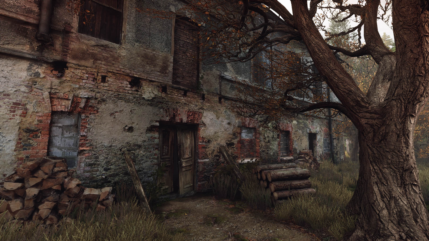
    You are probably tired from just reading about how much work it is to get the most out of photogrammetry, and will probably scratch your head when I tell you we’re actually not going for full photorealism. Take a look at this shot of a certain old house in our game:
    Photogrammetry - House
    All this work to make true-to-life assets and then we ‘break it’ with somewhat stylized lighting and postprocessing, and mixing scanned assets with traditionally crafted ones? What’s up with that?
    We didn’t scan all these assets for you to inspect every tiny pixel and marvel at technical excellence of our art pipeline. We went through all the hard work on these assets so that you can stop seeing assets and start seeing the world. Feeling the world. It may look photorealistic to some, it may seem magical to others, but if we did our scanning right, it should above all, feel right.
    And the end of the day, photogrammetry is a tool. Nothing less, but nothing more. It’s still up to designers and artists to decide what kind of world they are creating, and on what journey they want to invite the players.
    In our case, we’re making a weird fiction game, a dark tale, and not a documentary — and this needs to be supported by a certain visual style that goes beyond photorealism (and that is sometimes a bit harder to achieve than pure photorealism).
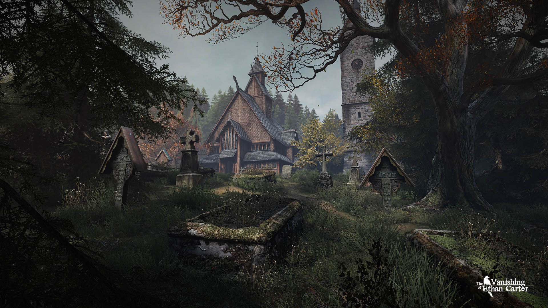
    And on that cue, here is a brand new screenshot from the journey that The Vanishing of Ethan Carter offers, an example of our artistic choice. Additionally, here are high quality wallpapers: 1920×1080 (16:9) and 2560×1600 (16:10).
    Photogrammetry - The Vanishing of Ethan Carter

Thursday, December 4, 2014

Tuesday, December 2, 2014

Google Cardboard Access / IOS accounts

Hey guys-
If anyone wants to use the Google Card Board please ask and you can borrow it. We might want to cut one more after learning from our first attempts. I forgot to ask if anyone wanted to use it.

Last call on the free IOS accounts. If you are interested and have not contacted me read the old post on this and get me the correct info.

Thx!

Mark
Dear AR Class, Come to ITP Big Screens this Friday at IAC. I would love for you all to see my project, The Fall of Erebus. Plus free food and drink!

Monday, December 1, 2014

google cardboard tutorial-

https://developers.google.com/cardboard/get-started

files

https://github.com/googlesamples/cardboard/

Tutorial

This document describes how to use the experimental VR Toolkit to create your own Virtual Reality (VR) experiences.

Android demo app: Treasure Hunt

The code examples in this tutorial are taken from the "Treasure Hunt" Android demo app.
Cardboard is a simple device that unlocks the power of your smart phone as a VR platform. Despite costing around $2, Cardboard can work with your phone to display 3D scenes with binocular rendering, track and react to head movements, and interact with apps through magnet input. The demo app “Treasure Hunt” illustrates these features. In the game, users look around a digital world to find and collect objects as quickly as possible. It’s a basic game, but it demonstrates the core features of Cardboard.

Game features

The "Treasure Hunt" game starts with instructions rendered as 3D text. Users are instructed to pull the magnet when they find an object.
This is what appears on screen. This will appear as a 3D scene when viewed in Cardboard.
When a user centers a cube in the middle of the screen, the cube indicates this by changing its color to yellow. When the user pulls the magnet while the cube is yellow, the user's score increases, and the cube moves to a new location.
The app uses OpenGL ES 2.0 to display objects. It demonstrates some basic features, such as lighting, movement in space, and coloring. It shows how to use the magnet as input, how to check if the user is looking at something, and how to render images by providing a different view for each eye.

Get the VR Toolkit JAR

To use the Cardboard API, download the VR Toolkit .jar file and include it in your project.

Edit the manifest

These excerpts from the demo app's manifest illustrate mandatory and recommended settings for a Cardboard app:
<manifest ...
    <uses-permission android:name="android.permission.NFC" />
    <uses-permission android:name="android.permission.VIBRATE" />
    ...
    <uses-sdk android:minSdkVersion="16"/>
    <uses-feature android:glEsVersion="0x00020000" android:required="true" />
    <application
            ...
        <activity
                android:screenOrientation="landscape"
                ...
        </activity>
    </application>
</manifest>
Note the following:
  • <uses-sdk android:minSdkVersion="16"/> indicates that the device must be running API Level 16 (Jellybean) or higher.
  • <uses-feature android:glEsVersion="0x00020000" android:required="true" /> indicates that the device must support OpenGL ES 2.0 to run the demo app.
  • android:screenOrientation="landscape" indicates that the activity's required screen orientation is "landscape." This is the orientation you must set for VR apps. The view used by the toolkit, CardboardView, only renders on fullscreen and landscape (landscape, reverseLandscape, sensorLandscape) modes.
  • Even though the demo app doesn't include it, the setting android:configChanges="orientation|keyboardHidden" is also recommended.
  • android.permission.NFC and android.permission.VIBRATE. You need the permission android.permission.NFC to access Cardboard's NFC tag, and the android.permission.VIBRATE permission to cause the phone to vibrate (which is how the demo app informs the user that something has happened).

Extend CardboardActivity

CardboardActivity is the starting point for coding a cardboard app. CardboardActivity is the base activity that provides easy integration with Cardboard devices. It exposes events to interact with Cardboards and handles many of the details commonly required when creating an activity for VR rendering.
Note that CardboardActivity uses sticky immersive mode, in which the system UI is hidden, and the content takes up the whole screen. This is a requirement for a VR app, since CardboardView will only render when the activity is in fullscreen mode. See Using Immersive Full-Screen Mode for more discussion of this feature.
The demo app's MainActivity extends CardboardActivity. MainActivity implements the following interface:
  • CardboardView.StereoRenderer: Interface for renderers that delegate all stereoscopic rendering details to the view. Implementors should simply render a view as they would normally do using the provided transformation parameters. All stereoscopic rendering and distortion correction details are abstracted from the renderer and managed internally by the view.

Get the CardboardView

All user interface elements in an Android app are built using views. The VR Toolkit provides its own view, CardboardView, which is a convenience extension of GLSurfaceView that can be used for VR rendering. CardboardView renders content in stereo. You initialize your CardboardView in your activity's onCreate() method:
private float[] mModelCube;
private float[] mCamera;
private float[] mView;
private float[] mHeadView;
private float[] mModelViewProjection;
private float[] mModelView;
private float[] mModelFloor;
private Vibrator mVibrator;
...

**
 * Sets the view to our CardboardView and initializes the transformation matrices we will use
 * to render our scene.
 * @param savedInstanceState
 */
@Override
public void onCreate(Bundle savedInstanceState) {
    super.onCreate(savedInstanceState);
    setContentView(R.layout.common_ui);
    CardboardView cardboardView = (CardboardView) findViewById(R.id.common_paperscope_view);
    // Associate a CardboardView.StereoRenderer with cardboardView.
    cardboardView.setRenderer(this);
    // Associate the cardboardView with this activity. 
    setCardboardView(cardboardView);
    mModelCube = new float[16];
    mCamera = new float[16];
    mView = new float[16];
    mModelViewProjection = new float[16];
    mModelView = new float[16];
    mModelFloor = new float[16];
    mHeadView = new float[16];
    mVibrator = (Vibrator) getSystemService(Context.VIBRATOR_SERVICE);
...
}

Render the view

Once you get the CardboardView you associate it with a renderer, and then you associate the CardboardView with the activity. Cardboard supports two kinds of renderers, but the quickest way to get started is to use CardboardView.StereoRenderer, which is what the demo app uses.
CardboardView.StereoRenderer includes these key methods:
  • onNewFrame(), called every time that app renders.
  • onDrawEye(), called for each eye with different eye parameters.
Implementing these is similar to what you would normally do for an OpenGL application. These methods are discussed in more detail in the following sections.

Implement onNewFrame

Use the onNewFrame() method to to encode rendering logic before the individual eyes are rendered. Any per-frame operations not specific to a single view should happen here. This is a good place to update your model. In this snippet, the variable mHeadView contains the position of the head. This value needs to be saved to use later to tell if the user is looking at treasure:
private int mGlProgram = GLES20.glCreateProgram();
private int mPositionParam;
private int mNormalParam;
private int mColorParam;
private int mModelViewProjectionParam;
private int mLightPosParam;
private int mModelViewParam;
private int mModelParam;
private int mIsFloorParam;
private float[] mHeadView;
...
/**
 * Prepares OpenGL ES before we draw a frame.
 * @param headTransform The head transformation in the new frame.
 */
@Override
public void onNewFrame(HeadTransform headTransform) {
    GLES20.glUseProgram(mGlProgram);
    mModelViewProjectionParam = GLES20.glGetUniformLocation(mGlProgram, "u_MVP");
    mLightPosParam = GLES20.glGetUniformLocation(mGlProgram, "u_LightPos");
    mModelViewParam = GLES20.glGetUniformLocation(mGlProgram, "u_MVMatrix");
    mModelParam = GLES20.glGetUniformLocation(mGlProgram, "u_Model");
    mIsFloorParam = GLES20.glGetUniformLocation(mGlProgram, "u_IsFloor");
    // Build the Model part of the ModelView matrix.
    Matrix.rotateM(mModelCube, 0, TIME_DELTA, 0.5f, 0.5f, 1.0f);
    // Build the camera matrix and apply it to the ModelView.
    Matrix.setLookAtM(mCamera, 0, 0.0f, 0.0f, CAMERA_Z, 0.0f, 0.0f, 0.0f, 0.0f, 1.0f, 0.0f);
    headTransform.getHeadView(mHeadView, 0);
    checkGLError("onReadyToDraw");
}

Implement onDrawEye

Implement onDrawEye() to perform per-eye configuration.
This is the meat of the rendering code, and very similar to building a regular OpenGL ES2 application. The following snippet shows how to get the view transformation matrix, and also the perspective transformation matrix. You need to make sure that you render with low latency. Otherwise EyeTransform contains the transformation and projection matrices for the eye. This is the sequence of events:
  • The treasure comes into eye space.
  • We apply the projection matrix. This provides the scene rendered for the specified eye.
  • The toolkit applies distortion automatically, to render the final scene.
private int mPositionParam;
private int mNormalParam;
private int mColorParam;
// We keep the light always position just above the user.
private final float[] mLightPosInEyeSpace = new float[] {0.0f, 2.0f, 0.0f, 1.0f};
...
/**
 * Draws a frame for an eye. The transformation for that eye (from the camera) is passed in as
 * a parameter.
 * @param transform The transformations to apply to render this eye.
 */
@Override
public void onDrawEye(EyeTransform transform) {
    GLES20.glClear(GLES20.GL_COLOR_BUFFER_BIT | GLES20.GL_DEPTH_BUFFER_BIT);
    mPositionParam = GLES20.glGetAttribLocation(mGlProgram, "a_Position");
    mNormalParam = GLES20.glGetAttribLocation(mGlProgram, "a_Normal");
    mColorParam = GLES20.glGetAttribLocation(mGlProgram, "a_Color");
    GLES20.glEnableVertexAttribArray(mPositionParam);
    GLES20.glEnableVertexAttribArray(mNormalParam);
    GLES20.glEnableVertexAttribArray(mColorParam);
    checkGLError("mColorParam");
    // Apply the eye transformation to the camera.
    Matrix.multiplyMM(mView, 0, transform.getEyeView(), 0, mCamera, 0);
    // Set the position of the light
    Matrix.multiplyMV(mLightPosInEyeSpace, 0, mView, 0, mLightPosInWorldSpace, 0);
    GLES20.glUniform3f(mLightPosParam, mLightPosInEyeSpace[0], mLightPosInEyeSpace[1],
            mLightPosInEyeSpace[2]);
    // Build the ModelView and ModelViewProjection matrices
    // for calculating cube position and light.
    Matrix.multiplyMM(mModelView, 0, mView, 0, mModelCube, 0);
    Matrix.multiplyMM(mModelViewProjection, 0, transform.getPerspective(), 0, mModelView, 0);
    drawCube();
    // Set mModelView for the floor, so we draw floor in the correct location
    Matrix.multiplyMM(mModelView, 0, mView, 0, mModelFloor, 0);
    Matrix.multiplyMM(mModelViewProjection, 0, transform.getPerspective(), 0,
        mModelView, 0);
    ...
}

Cardboard input hardware

Cardboard includes the following hardware components for interacting with an Android app:
  • Magnets are used to create a push button. When you push the magnet, the magnetic field changes and is detected by the magnetometer of your phone. This is used to trigger operations in the demo app. This behavior is provided by the parent activity (CardboardActivity) implementation of the MagnetSensor.OnCardboardTriggerListener interface.
  • An NFC tag. When you insert a device that has the Android demo app on it into the Cardboard device, NFC triggers the launch of the demo app. This behavior is provided by the parent activity (CardboardActivity) implementation of the NfcSensor.OnCardboardNfcListener interface.
You can programmatically modify your app's interactions with these components, as described below.

Listen for magnet pulls

To provide custom behavior when the user pulls the magnet, override CardboardActivity.onCardboardTrigger() in your app's activity. In the treasure hunt app, if you found the treasure and pull the magnet, you get to keep the treasure:
private Vibrator mVibrator;
private CardboardOverlayView mOverlayView;
...
/**
 * Increment the score, hide the object, and give feedback if the user pulls the magnet while
 * looking at the object. Otherwise, remind the user what to do.
 */
@Override
public void onCardboardTrigger() {
    if (isLookingAtObject()) {
        mScore++;
        mOverlayView.show3DToast("Found it! Look around for another one.\nScore = " + mScore);
        ...
    } else {
        mOverlayView.show3DToast("Look around to find the object!");
    }
    // Always give user feedback
    mVibrator.vibrate(50);
}

/**
 * Check if user is looking at object by calculating where the object is in eye-space.
 * @return
 */
private boolean isLookingAtObject() {
    float[] initVec = {0, 0, 0, 1.0f};
    float[] objPositionVec = new float[4];

    // Convert object space to camera space. Use the headView from onNewFrame.
    Matrix.multiplyMM(mModelView, 0, mHeadView, 0, mModelCube, 0);
    Matrix.multiplyMV(objPositionVec, 0, mModelView, 0, initVec, 0);

    float pitch = (float)Math.atan2(objPositionVec[1], -objPositionVec[2]);
    float yaw = (float)Math.atan2(objPositionVec[0], -objPositionVec[2]);
    ...
    return (Math.abs(pitch) < PITCH_LIMIT) && (Math.abs(yaw) < YAW_LIMIT);
}

Customize NFC behavior

As described in Extend CardboardActivity, the CardboardActivity base class implements the NfcSensor.OnCardboardNfcListener interface. This method is called whenever a phone is inserted in a Cardboard.
You can override the NfcSensor.OnCardboardNfcListener methods onInsertedIntoCardboard() and onRemovedFromCardboard() methods to to switch VR (binocular) mode on and off. Thus you could make the treasure hunt work without Cardboard too, by disabling VR mode. For example:
// Enable VR mode when phone is inserted into Cardboard
@Override 
public void onInsertedIntoCardboard() {
  this.cardboardView.setVRModeEnabled(true);
}
// Disable VR mode when phone is removed from Cardboard
@Override 
public void onRemovedFromCardboard() {
  this.cardboardView.setVRModeEnabled(false);
}

Adding stereo rendering to Metaio for Google Cardboard.

Adding stereo rendering to Metaio for Google Cardboard.

We will do this w the Metaio creator

 http://dev.metaio.com/sdk/tutorials/see-through-glasses/

See-through Glasses

General

In order to support see-through glasses, such as the Epson Moverio BT-200 glasses, the Metaio SDK has stereo rendering support built in with version 5.2 and newer. If the stereo rendering mode is enabled, the scene is rendered twice from two slightly different perspectives. The output of these two renderings is displayed in a so called split screen mode that is supported by most 3D output devices such as phones with 3D capable displays or stereo glasses. It might be necessary to use some device vendor specific API to enable the 3D display or glass to work in split screen mode together with the Metaio SDK.
To test the stereo rendering, you can enable it on any device. You will just see the screen split in the middle, showing one rendering on the left and another one on the right side.
The Metaio SDK is optimized for stereo mode, which is available on the Epson Moverio BT-200 glasses, but will run perfectly well in mono mode on devices such as Google Glass, Vuzix M100, etc. There is a dedicated tutorial explaining how to run the Metaio SDK on Google Glass.

Enabling Stereo Rendering

There is only one method that needs to be called to initially enable stereo rendering

Android (Java)

metaioSDK.setStereoRendering(true)

Adjusting the Rendering Angles [SDK 5.3 and older]

To adjust the position of the virtual cameras which render the scene from two different angles, two more methods are provided by the SDK.

Android (Java)

//left camera
Vector3d positionLeft = new Vector3d(0.0f, 0.0f, 0.0f);
Vector3d upVectorLeft = new Vector3d(0.0f, 1.0f, 0.0f);
Vector3d lookAtLeft = new Vector3d(0.0f, 0.0f, -100.0f);
metaioSDK.setStereoRenderingLeftCameraTransformation(positionLeft,upVectorLeft,lookAtLeft);
 
//right camera
Vector3d positionRight = new Vector3d(-10.0f, 0.0f, 0.0f);
Vector3d upVectorRight = new Vector3d(0.0f, 1.0f, 0.0f);
Vector3d lookAtRight = new Vector3d(0.0f, 0.0f, -100.0f);
metaioSDK.setStereoRenderingRightCameraTransformation(positionRight,upVectorRight,lookAtRight);

Adjusting the Rendering Angles [SDK 5.5 to 6.0]

With SDK 5.5, we superseded the old methods setStereoRendering{Left,Right}CameraTransformation by setHandEyeCalibration, which allows you to influence the hand-eye calibration (and thus the viewing angle of left/right eye on 3D-capable devices) using a translation and a rotation component.
The "hand-eye calibration" defines the transformation from camera space to eye space, which is necessary to render AR correctly e.g. on devices like smart glasses where the camera and eye projector positions and orientations (viewing directions) are distinct. So if for instance, a device has one projective display for each human eye, and a camera positioned on the right temple of the glasses, the translation part for each eye's calibration would most probably be positive (e.g. 10mm for right eye, and 70mm for left eye).
The setStereoRendering(true) call automatically applies an initial hand-eye calibration for known devices. For example, SDK 5.5 introduced a calibration for the Epson Moverio BT-200 glasses. Mind however that SDK 6.0 does not automatically apply a calibration anymore, since we found that BT-200 devices are not manufactured equally and hence there is a need for per-device calibration. Please check the changelog for more updates on this.
In the example code, we use contrived values. They should be replaced by the values for the actual device in a real world scenario, or even better: use SDK 6.0.1 or newer, together with the recommended approach as documented below.

Android (Java)

// Adjust stereo calibration (i.e. difference in view of camera vs. left/right eye).
// These are contrived example values. Real values should be gathered by an exact
// calibration. Note that for typical scenarios, e.g. AR/VR glasses where the camera has
// a translation to left/right eye, the camera image is still rendered as for the mono
// case (it is not transformed by the hand-eye calibration to look correct). Therefore
// on glasses, see-through mode should be enabled (see below).
// This is just a contrived example. The values are overwritten below, using the recommended
// approach.
metaioSDK.setHandEyeCalibration(
 new Vector3d(70f, 0f, 0f),
 new Rotation(0f, -18f * (float)Math.PI/180f, 0f),
 ECAMERA_TYPE.ECT_RENDERING_STEREO_LEFT);
metaioSDK.setHandEyeCalibration(
 new Vector3d(10f, 0f, 0f),
 new Rotation(0f, 7f * (float)Math.PI/180f, 0f),
 ECAMERA_TYPE.ECT_RENDERING_STEREO_RIGHT);

Adjusting the Rendering Angles [SDK 6.0.1 and newer]

The "hand-eye calibration" defines the transformation from camera space to eye space, which is necessary to render AR correctly e.g. on devices like smart glasses where the camera and eye projector positions and orientations (viewing directions) are distinct. So if for instance, a device has one projective display for each human eye, and a camera positioned on the right temple of the glasses, the translation part for each eye's calibration would most probably be positive (e.g. 10mm for right eye, and 70mm for left eye).
SDK version 6.0.1, together with Toolbox for Android 6.0.1, introduce a new and recommended approach to set the hand-eye calibration.
Toolbox allows creation of calibrations directly on the device, e.g. supported for the Epson Moverio BT-200. After you've finished calibrating a device, Toolbox stores a calibration file at a fixed path on the device (typically "/sdcard/metaio/hec/hec.xml"), where the SDK can load it by simply calling setHandEyeCalibrationFromFile() without parameters. Since stereo devices may need per-device calibration (such as the BT-200, since they are not manufactured identically), we recommend the following approach to set the hand-eye calibration (in this order, exit if a step succeeds):
  1. Load your own, exact calibration (calibration XML file created with Toolbox 6.0.1 or newer), i.e. you as developer provide a calibration file. Note that the path to "hec.xml" doesn't actually exist in this example; it's only there to show how to apply a custom calibration file.
  2. Load calibration XML file from default path, i.e. in case the user has used Toolbox to calibrate (result file always stored at same path).
  3. Load calibration built into Metaio SDK for known devices (may not give perfect result because stereo glasses can vary).
Depending on your use case, you may want to skip step 1, or extend it with a mapping between device identifier and calibration file. Check the stereo calibration article for more ideas.

Android (Java)

final File calibrationFile = AssetsManager.getAssetPathAsFile(this, "TutorialStereoRendering/Assets/hec.xml");
 
if ((calibrationFile == null || !metaioSDK.setHandEyeCalibrationFromFile(calibrationFile)) &&
 !metaioSDK.setHandEyeCalibrationFromFile())
{
 metaioSDK.setHandEyeCalibrationByDevice();
}

Importance of adjustments for stereo devices

A hand-eye calibration ensures the augmentation, e.g. a 3D model, is displayed at the correct position and scale so that the human eye recognizes the left/right half images (imagine the screenshot below without the camera image) as one "real" object. Therefore, in contrast to mono rendering (AR for mobile phones or desktops), it is absolutely important to configure tracking in a way that physical scale is correct. This means if you are for instance tracking a magazine cover of physical size 210x297mm, but forget to specify the size of the reference image, the Metaio SDK will take the dimensions in pixels of the reference image as size in millimeters, which is in most cases not correct. Instead, you must specify the physical size in the tracking configuration - for markerless tracking, it would look like so:
<ReferenceImage WidthMM="114" HeightMM="114">metaioman_target.png</ReferenceImage>
For ID marker tracking, like this:
<MarkerParameters><MatrixID>1</MatrixID><Size>80</Size></MarkerParameters>
For 3D map tracking, you should use Metaio Toolbox to record, and then adapt the map to millimeter coordinates ("Align map" feature).
If you develop for a device that requires a hand-eye calibration, e.g. the BT-200, and tracking is not configured to match physical millimeter coordinates, you will see a wrongly scaled and shifted pose in the best case, or in the worst case the human eye will recognize e.g. an augmented 3D model as two distinct objects.
The reason is that, if the distance between camera and trackable image is not recognized correctly (e.g. SDK thinks it's 300mm when it's actually 700mm), the hand-eye calibration will influence the position of the augmented 3D objects more or less than it should, which leads to the effects just described.

See Through

In stereo rendering mode, displaying the camera image does not make much sense. Therefore it is recommended to enable the see through mode with setSeeThrough(true). For debugging purposes, see through can be disabled with setSeeThrough(false) in order to always render the camera image – which will however not be aligned to the augmentation in case a hand-eye calibration is set.

Android (Java)

// Enable see through mode (e.g. on glasses)
metaioSDK.setSeeThrough(true);
metaioSDK.setSeeThroughColor(0, 0, 0, 255);